Visualizing CubeSat Dynamics: Progress on My MEng Project
Published:
This page provides an overview of the progress made on the Attitude Determination and Control Subsystem (ADCS) of the DigiCube project for attendees of the Queen Mary University of London Industrial Liaison Forum being held on 5th March 2025.
Project Overview
The DigiCube project aims to replicate the key subsystems of a cube satellite within a simulated Low Earth Orbit environment. This digital twin will support future planning, design, assembly, and operation of CubeSat missions - including a potential mission originating within QMUL.
Among all the subsystems modelled within DigiCube, the Attitude Determination and Control Subsystem (ADCS) is positioned as one of the most critical and complex. This system is responsible for the orientation of the satellite, affecting:
- Drag forces
- Thermal effects
- Power generation
- Telemetry efficiency
- Orbital manoeuvring capabilities
Subsystem Architecture Development
To facilitate the design of the ADCS, a review of historic systems was conducted and utilised to create a unique system architecture for the DigiCube ADCS. This began with an analysis of two reference satellites:
Explorer-35 (NASA, 1967)
- Simple open-loop precession control with ground validation
- Basic sensor and actuator systems (sun sensors and thrusters)
- Emphasised the importance of nutation damping in spin-stabilised satellites
Sentinel-2 (ESA, Modern)
- Advanced multi-mode control system with fine pointing capabilities
- Sophisticated sensor fusion and state estimation
- Multiple operational modes for different mission phases
- Integrated power management through solar array tracking
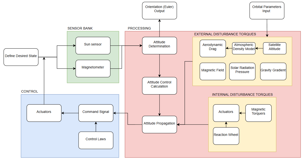
Based on this research, a comprehensive system architecture diagram was created, highlighting the key components of the simulation as well as the data inputs and outputs:

Current Simulation Features
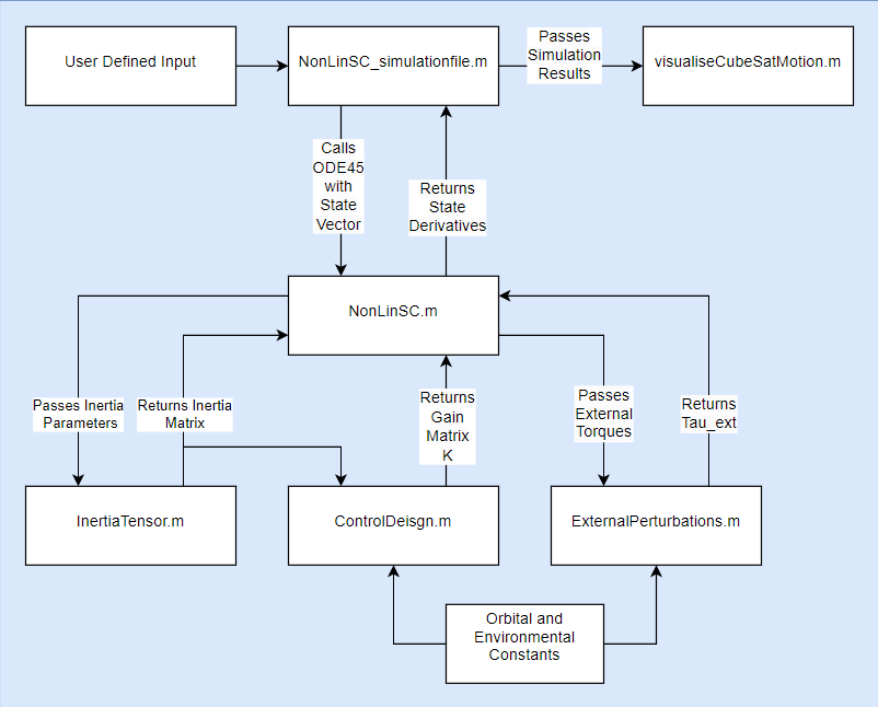
The MATLAB simulation provides a structured approach to modelling CubeSat attitude dynamics and orbital mechanics. It currently implements:
Quaternion-Based Attitude Representation: Ensuring numerically stable orientation tracking across all possible satellite attitudes without gimbal lock issues.
- Dual Control Modes:
- Detumbling Control: Quaternion feedback controller for stabilisation after deployment or during recovery operations.
- Earth Observation Tracking: Advanced pointing control to maintain nadir-facing orientation for Earth observation applications.
3D Visualisation: Real-time rendering of CubeSat orientation over time within its orbital path, allowing for intuitive understanding of the satellite’s behaviour, with capabilities for animation playback and video export.
- Orbital Mechanics Modelling: Simplified representation of satellite motion in Low Earth Orbit, including:
- Calculation of orbital parameters (semi-major axis, eccentricity, inclination, etc.)
- Position tracking relative to Earth
- Proper visualisation of orbital trajectory
- Environmental Disturbance Modelling: External torques that affect satellite orientation including:
- Gravity gradient effects (torques caused by Earth’s gravitational field)
- Aerodynamic drag (particularly important in Low Earth Orbit)
- Residual magnetic interactions (between satellite components and Earth’s magnetic field)
This setup establishes a foundation for integrating more advanced control and sensing capabilities as the project progresses.

Simulation Results
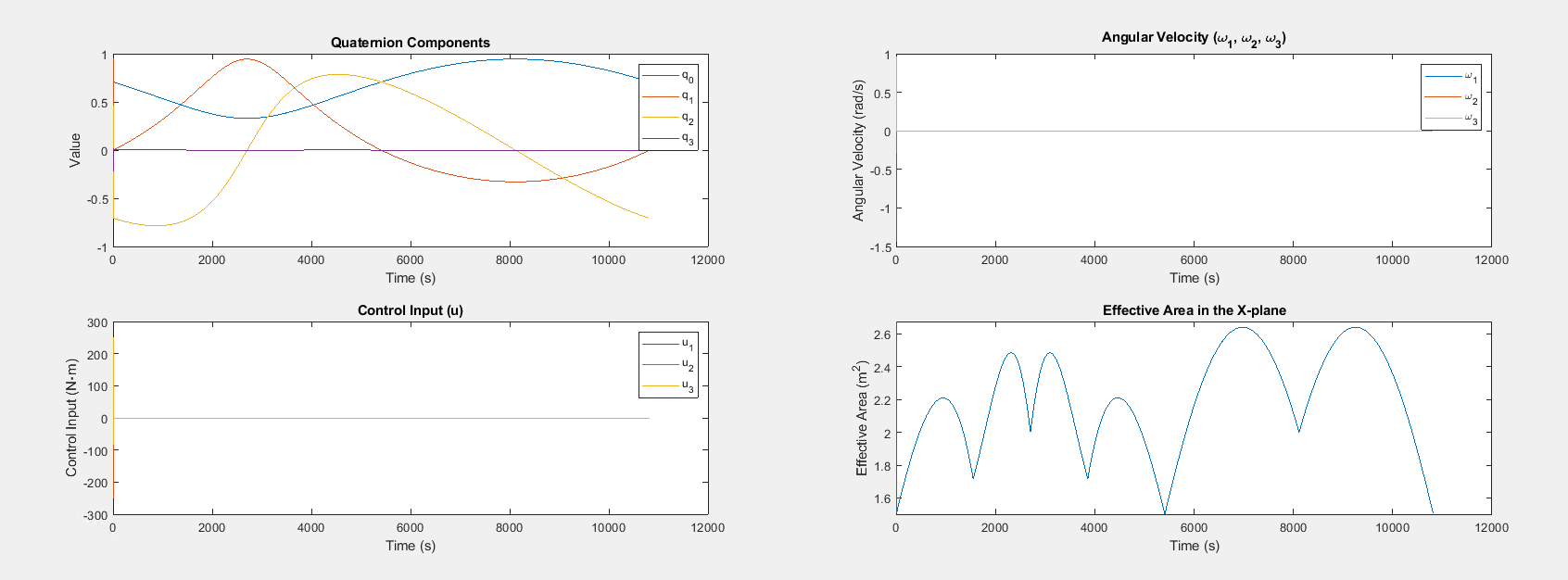
The CubeSat’s behaviour under quaternion feedback control has been analysed, with key outputs including:
Orientation Evolution
The simulation tracks and plots the CubeSat’s angular motion over time, demonstrating how the satellite responds to both control inputs and environmental disturbances.Angular Velocity Decay
The implemented detumbling algorithm effectively reduces angular rates, bringing the satellite to a stable attitude from an initially tumbling state.Control Torque Analysis
The control algorithms generate torques that are logged and plotted, providing insight into the control effort required for different manoeuvres.Effective Area Calculation
The simulation tracks the effective cross-sectional area of the satellite as it rotates, which is critical for accurate drag modelling in LEO.Earth-Tracking Performance
When in Earth observation mode, the satellite continuously reorients to keep its designated instrument facing Earth, with performance metrics captured in quaternion error tracking.
Output Plots

Video Demonstration
The following video demonstrates the CubeSat’s simulated behaviour in orbit, showing both detumbling and Earth-tracking capabilities:
Interactive Simulation Features
The simulation includes several interactive elements to enhance user experience and educational value:
Control Mode Selection: Users can choose between detumbling and Earth observation tracking modes depending on the mission scenario they wish to simulate.
Custom Orientation Targets: For detumbling mode, users can define specific desired quaternion orientations to test different pointing requirements.
Simulation Duration Control: The simulation length can be adjusted to study both short-term dynamic responses and long-term orbital effects.
Interactive Visualisation: The 3D visualisation includes:
- Play/pause controls for animation
- A time slider for manual scrubbing through the simulation
- Video export capabilities for presentations
- Realistic Earth and orbit path rendering
Next Steps
The upcoming development phases will focus on enhancing the CubeSat model with:
Actuator Integration: Implementing realistic models of reaction wheels and magnetorquers for active attitude control, including their operational constraints and failure modes.
Sensor Simulation: Modelling gyroscopes, sun sensors, and magnetometers for attitude determination, including sensor noise and calibration errors to ensure realistic performance.
Refined Environmental Modelling: Enhancing disturbance torque models with high-fidelity space environment effects, including solar radiation pressure and magnetic field variations.
- Advanced Control Laws: Testing and optimising various ADCS control strategies, including:
- Enhanced detumbling algorithms
- Fine pointing control
- Momentum management
- Target tracking with time-varying requirements
- Power Budget Integration: Connecting the ADCS simulation with power subsystem models to analyse the energy requirements for different attitude control scenarios.
Conclusion
This milestone brings the CubeSat digital twin closer to real-world applicability. The integration of quaternion-based attitude control, realistic orbital mechanics, and interactive visualisation tools creates a comprehensive platform for CubeSat mission planning and operations.
The current implementation successfully demonstrates both stabilisation and Earth-observation capabilities within a realistic orbital environment, providing valuable insights for future CubeSat mission development at QMUL.
For further discussions or collaboration opportunities, please contact j.hubbard@se21.qmul.ac.uk.
Stay tuned for more updates! 🚀
